Friday, March 26, 2010

Final Project - knowledge patterns


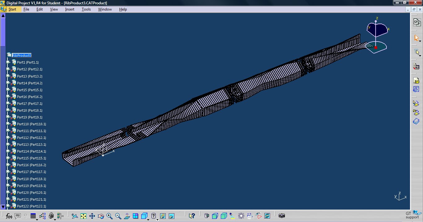
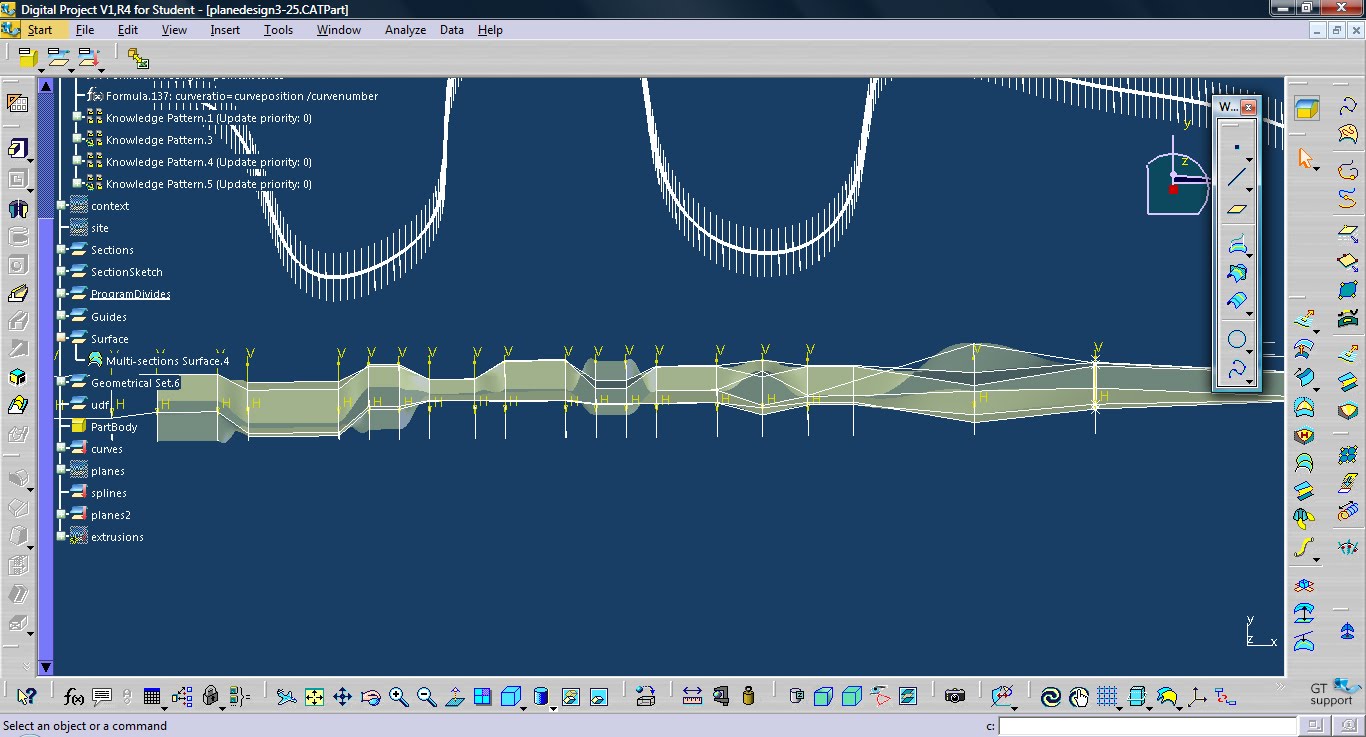
I finally figured out how to use a knowledge pattern on my project instead of a document template. I was able to set up two udfs which place a number of planes along two splines which are always perpendicular to the lofted surface. A third udf then intersects the planes from the first spline with the lofted surface, and creates a series of profiles. The udf then measures the distance between the planes of the second spline, and extrudes the profile curve that distance. The result of this is that by adjusting the splines I can control both the density and width of the bands. The more extreme the curve of the splines are, the closer the planes are together. If a I want a portion of the surface to become dense, I can adjust the splines so that they are steep at that portion of the surface.


Script for plotting planes on spline:


let d1(planeudfcurve)
let i (integer)

i=1

for i while i <= curvenumber
{
d1 = CreateOrModifyTemplate("planedesigncatalog|planeudfcurve", curves ,`Relations\Knowledge Pattern.1\planeudfcurve` ,i)
d1.axis = `yz plane`
d1.curve = `Geometrical Set.6\Sketch.1\Output.1 (Spline.1)`
d1.curvernumber = curvenumber - 1
d1.curveposition = i - 1

EndModifyTemplate(d1)
d1.Name = "CRV" + ToString(i)
}

Script for plotting planes on spline 2:

let d1(planeudfcurve2)
let i (integer)

i=1

for i while i <= curvenumber
{
d1 = CreateOrModifyTemplate("planedesigncatalog|planeudfcurve2", planes2 ,`Relations\Knowledge Pattern.4\planeudfcurve2` ,i)
d1.axis = `yz plane`
d1.curve = `Geometrical Set.6\Sketch.1\Output.5 (Spline.2)`
d1.curvernumber = curvenumber - 1
d1.curveposition = i - 1

EndModifyTemplate(d1)
d1.Name = "CRV" + ToString(i)
}


Script for intersecting planes with surface, and then extruding them


let d1(planeudfsec2)
let i (integer)

i=1

for i while i <= (curvenumber-1)
{
d1 = CreateOrModifyTemplate("planedesigncatalog|planeudfsec2",extrusions , `Relations\Knowledge Pattern.5\planeudfsec2` ,i)
d1.surface =`Surface\Multi-sections Surface.4`
d1.line = context\Line.19
d1.plane = `Relations\Knowledge Pattern.1\planeudfcurve` ->GetItem(i)
d1.planeA = `Relations\Knowledge Pattern.4\planeudfcurve2` ->GetItem(i)
d1.planeB = `Relations\Knowledge Pattern.4\planeudfcurve2` ->GetItem(i+1)

i = i+1

EndModifyTemplate(d1)
d1.Name = "CRV" + ToString(i)
}

Wednesday, March 24, 2010

too much document template

For my midterm review last friday, I continued working with the document template I set up in the last post. It proved very laborious (near 200 instantiations), but still a lot more accurate and useful than the physical model I was working on. Since then I have started working with a user defined feature which has proved to be much easier and more efficient to use. I'll post that soon.


Wednesday, March 17, 2010

Tuesday, March 16, 2010

Final Project Change


I settled on a form for my studio project this week, and I think that digital project will be able to help me with it, so i have decide to make it my final project for paramod, instead of using my project from smart surfaces. My studio project is situated on a narrow strip of land by the LA river. It consists of a series of programs such as a restaurant, farmers market, and store, which will utilize food grown on the banks of the river. The programs are lodged in a tube which gradients from total enclosure to partial enclosure through the variation of a repeating element. A picture of the concept model for the project is show above. For Wedesday's pinup I am going to try to replicate the concept model by using a document template. I think the framework will be the most challenging part of this model, since the part is essentially just a bent rectangle.

Wednesday, March 10, 2010

Final Project


For the final project I am planning on building off of an earlier studio project for Smart Surfaces. The original project was a series of modules which controlled the amount of light entering a space - similar to blinds. I can use digital project to make the surface parametric, and maybe explore possibilities for inserting it into existing buildings.

Wednesday, February 24, 2010

Helios House Knowledge Pattern

For this case study I mimicked the design of the helios house in LA. On my first attempt, I simply triangulated a column, but there was not as much differentiation in the surface as in the surface of the helios house. I then replaced the triangulation with a pyramid shape, which is not exactly the same as the helios surface, but looks similar to it because of its roughness.


Knowledge Pattern

Here is the first knowledge pattern which I created from the Paramod tutorial.


Wednesday, February 10, 2010

Document Templates

For this tutorial I create a tube which is defined by four points at each end. The thickness of the tube is proportional to its length - the shorter the tube the thicker it is. The ratio of thickness to length is controlled by global parameters at each end, so the diameter of the opening can be different at each end of the tube. I ran into a few problems when I tried editing the original framework, and when I updated the original parameters. In one instance, I changed the framework in a way which caused some of the components to turn red. Also, after saving the product and reopening it, all of my parts had lighting bolts next to them in the tree, and would not update with the global parameters.


Tuesday, February 2, 2010

Power Copy - Yas Hotel

For this assignment I modeled the facade of the Yas hotel, which consists of a series of diamonds. I first set up two overlapping grids which created a diamond pattern, and then projected that onto a curved surface. I created a diamond shaped surface between the points, and gave it a parameter which allowed it to open on one side, like the panels in the yas hotel facade. I then power copied this shape across the entire grid.


Wednesday, January 27, 2010

Dynamic Tower - part 2

CLICK IMAGE TO VIEW ANIMATION


So here is my model of the assembled parts I created in my previous post. For some reason I am having errors with my constraints when I save them. The modules should all rotate at the same angle. This was working when I first set the relationships up, but when I saved the file and reopened it it read the parameters differently for some reason. I also ran into an issue with output features. When making my parts, I would use output features to generate the solids, but sometimes the output features would disappear after they had been used to generate a solid. This created a problem because i could not use them to create other solids or pockets.

Sunday, January 24, 2010

Dynamic Tower

This week I chose to make the dynamic tower, which is composed of a series of core modules stacked on top of each other, with floor plates which slide over them. I modeled the core and floor module, and then created a variation of the core module which will allow the tower to bend.


After making these parts I created a product and am currently working on assembling them. I am linking the floors to the core with a angle parameter, so i can control the rotation, and the angle of the bending cores is controlled by a parameter in the part, so the amount of bending can be controlled.